Game Boy DMG-01 Headphone Jack Replacement Board — Audio & Speaker Fix
Brand-new modern board that cures the classic dead-jack / no-speaker-sound DMG fault. Base, Pro line-out, or bare PCB.
$20.00
Stocking up on bare boards? Buy 2 or more and take 40% off each.
Finally, a real fix for a broken Game Boy headphone jack
If you’re restoring an original DMG-01 Game Boy, you’ve probably hit a common, maddening fault: a corroded, failing headphone jack. When it goes, the internal speaker often stops working entirely — the console wrongly thinks headphones are plugged in and mutes itself. For years the only fix was to scavenge another used, 30-year-old part from a donor console and hope it lasted.
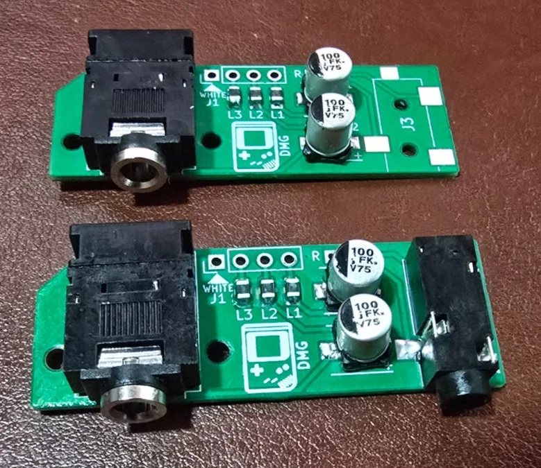
This is a brand-new, modern replacement board that solves the problem for good. It’s built on the excellent open-source, CC0-licensed design by wiretap-retro, and it uses all-new components — including an all-new CUI SJ-3566AN jack, not a salvaged one. I order the custom PCBs, hand-assemble the tiny surface-mount parts, and bench-test every assembled board before it ships. Drop it in and your Game Boy’s sound system works the way it should again.
This uses a modern jack — not your old one. The new CUI jack is an integral part of the board, so you reuse only the four wires from your old harness, not the original headphone jack (which is usually the failed part you’re replacing in the first place). Bare-board builders, note this too: the PCB is laid out for the modern CUI jack’s footprint and will not accept an original Nintendo jack.
Three versions — pick from the dropdown
- Base (assembled & tested) — a direct 1-for-1 replacement for the original board. Restores both headphone output and internal speaker function.
- Pro Line-Out (assembled & tested) — everything the Base does, plus a second 3.5mm jack giving a dedicated, clean line-level output. It bypasses the Game Boy’s internal amplifier, so it’s ideal for chiptune artists, musicians, and anyone recording high-quality audio straight from the console.
- Bare Board (PCB only) — just the unpopulated PCB, for folks who’d rather source the components and assemble it themselves. (Want the bill of materials? It’s in the open-source project linked below.) Buying two or more bare boards? Take 40% off each — and they ship together, so you save on shipping too.
What’s included
- Base: one (1) assembled, tested replacement board.
- Pro Line-Out: one (1) assembled, tested “Pro” board with both jacks populated, plus two (2) pre-stripped 26 AWG wires (one red, one black) for the line-out connection.
- Bare Board: one (1) unpopulated PCB.
Note: the original 4-wire harness is not included — you’ll desolder the wires from your old board and reuse them (they don’t even need to leave their clips). If yours are damaged and you need a fresh set, message me before ordering and I can usually include them free.
How hard is this? Read before you buy
This is a do-it-yourself modding part, not a plug-in module. Here’s the honest picture so there are no surprises:
- Soldering required. The Base install is beginner-to-intermediate: you desolder four wires from your old board and resolder them to this one — through -hole-style pads, not fine SMD work. If you’ve soldered before, you can do this. The Pro version is a step up (intermediate): you also solder two fine wires to the board and to the volume-wheel pins on the mainboard.
- A permanent internal case trim. The new jack is a couple of millimeters larger than the original, so you’ll shave away a small plastic “box” inside the shell so it fits. This is entirely internal and invisible from the outside — see the before/after photos. The Pro version additionally needs one small hole drilled in the shell for the second jack.
- No returns on DIY kits. Because installation involves soldering and a permanent case modification, returns can’t be accepted. Confirm your Game Boy otherwise works before you start, and make sure you’re comfortable with the steps below.
Tools you’ll need
- Soldering iron
- Solder (leaded recommended) and flux
- Desoldering wick/braid
- Tri-wing screwdriver (external case screws) and Phillips screwdriver (internal)
- Flush cutters (for the internal case trim)
Optional but recommended: a file or sandpaper to smooth the trimmed plastic, a hobby knife, and a multimeter for continuity checks.
Pro version also needs: a drill or rotary tool (Dremel) to make a clean hole for the second jack. Flush cutters can work in a pinch but won’t look as tidy.
Installation — Base version
- Disassemble. Open your DMG Game Boy.
- Desolder the old board. Apply flux and use desoldering braid to wick as much old solder as you can from the four wire pads on the back of the original headphone board.
- Free the wires. Gently heat each pad while lifting the board; the wires should release easily. Don’t pull or force them — that can damage the wires or the mainboard pads. The original harness can stay in its clips.
- Fit the new board. Insert the four wires into the new board in the same orientation. The white wire’s pad is clearly marked.
- Solder. Flux and solder the four wires, aiming for clean, shiny joints, and check for bridges between pins. The capacitors may leave the board sitting at a slight angle — that’s normal.
- TEST before you cut anything. You should get speaker audio with nothing plugged in, and headphone audio when headphones are inserted.
- Trim the case. With flush cutters, carefully cut away the plastic “box” inside the shell that surrounds the jack (see the photos for the finished look). Avoid the nearby screw posts; a little filing/scraping gets a perfect fit.
- Reassemble. Line the board up with the screw holes and start the screws. Don’t over-tighten — the board seats securely without being torqued down, and a slight angle is fine.
Additional steps — Pro Line-Out version
- Attach the line-out wires. Before trimming the case, solder the two included wires to the pads marked R and L: twist the bare end, insert it into the hole, flux, and solder.
- Connect to the mainboard. Find the volume wheel on the Game Boy’s mainboard. The R (red) wire goes to the top pin of the volume-wheel connector; the L (black) wire goes to the second pin from the top. Tin the wires first (see the mainboard photo).
- Test the line-out. Confirm you’re getting clean audio from the new jack.
- Drill the shell. In addition to the main-jack trim, drill a clean hole in the shell so the line-out jack is accessible from outside.
Open-source design — and the BOM
This board is the open-source wiretap-retro “Gameboy DMG Headphone Jack PCB” project, released under CC0. If you want the full design, schematic, or bill of materials — handy for the bare-board builders — it’s all public on GitHub: github.com/wiretap-retro/Gameboy-DMG-Headphone-Jack-PCB. I just manufacture the boards with all-new parts, assemble, and test them. Questions about the design or the install are always welcome.
About the maker
I’m an electrical engineer and long-time hobbyist with a passion for vintage electronics, especially classic video games. The items I sell are projects from my own workshop. Everything is guaranteed working on arrival and in the state described. Thanks for looking.
Specifications
| Compatibility | Original Nintendo Game Boy DMG-01 only |
|---|---|
| Design | Open-source wiretap-retro design, CC0 — all-new components, hand-assembled and tested |
| Fixes | Dead headphone jack / no internal speaker sound on the original DMG-01 |
| Headphone Jack | All-new CUI SJ-3566AN — not a salvaged 30-year-old part |
| Install Difficulty | Beginner–intermediate soldering + a hidden internal case trim (Pro adds one drilled hole) |
| Pro Feature | Second 3.5mm jack with amp-bypassed line-level output for recording / chiptune |
| Versions | Base (1-for-1 replacement), Pro (adds a clean line-out), or bare PCB |
Similar items
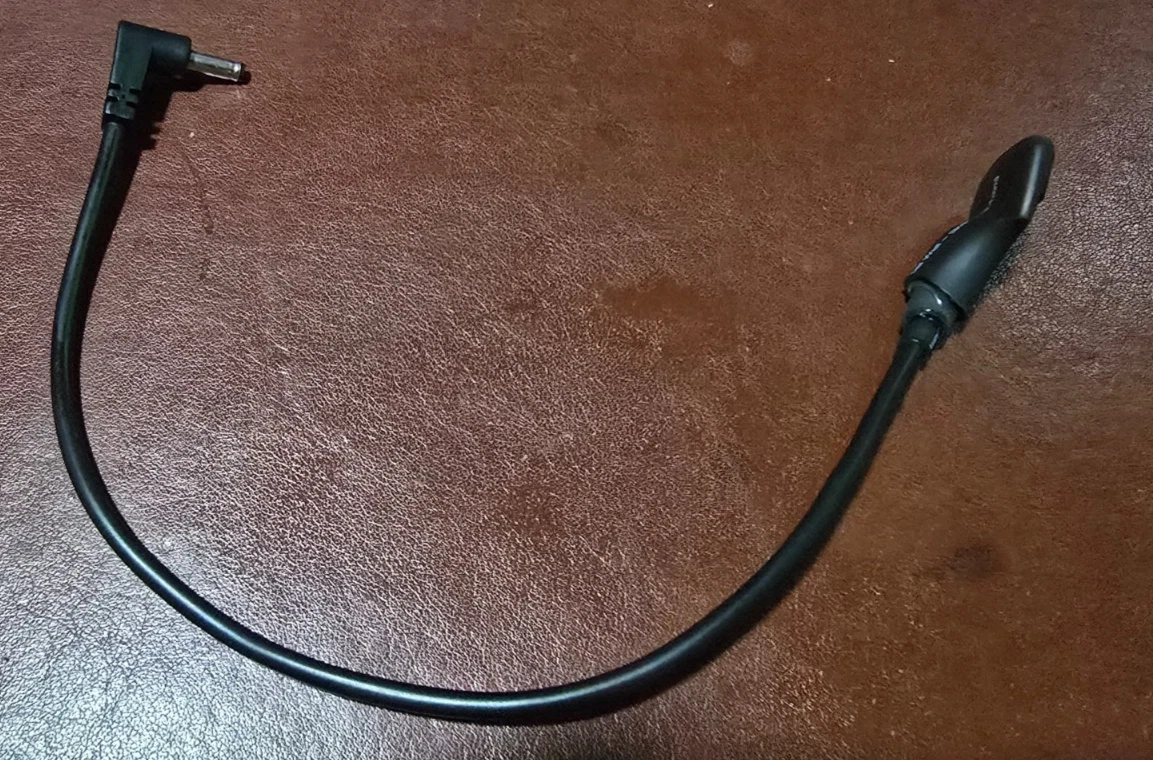
Prototype USB-C Power Adapter — Sega Game Gear or Nintendo Game Boy (Working Seconds)
Fully working early-build dongles at a steep discount. Looks vary (heatshrink or an early case), function is identical. $10 each, or two for $15.
$10.00 (plus 1 other variant)
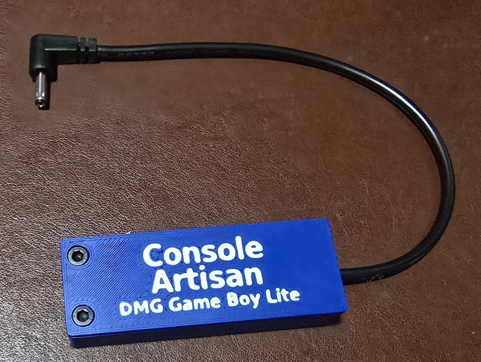
USB-C 5V Power Adapter for Original Nintendo Game Boy (DMG-01) (Lite)
Hand-built and enclosed. Runs on any 5V USB port — no USB-PD required. The simple, best-value way to power a DMG.
$20.00
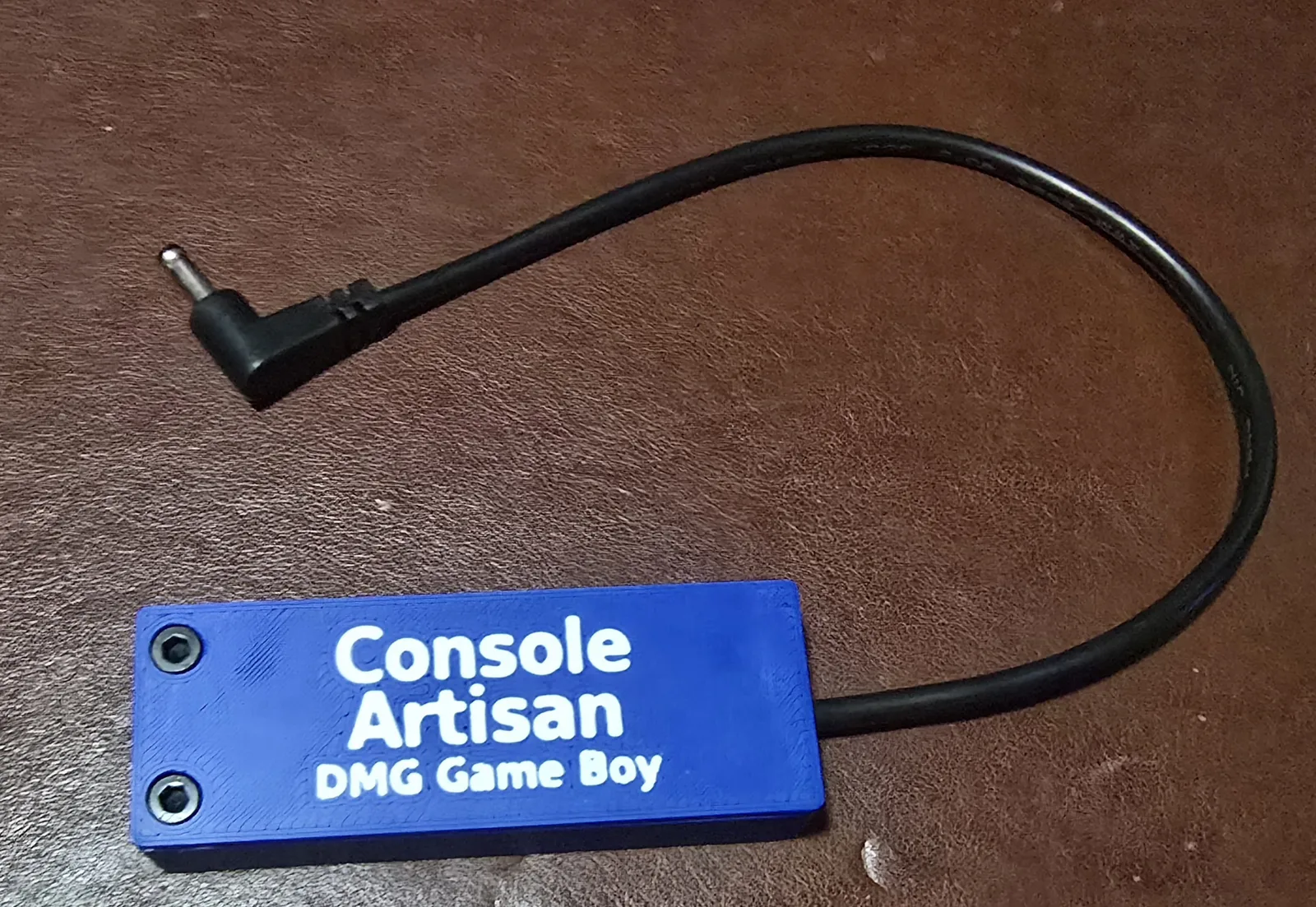
USB-C 6V Power Adapter for Original Nintendo Game Boy (DMG-01)
Hand-built, enclosed, and labeled — true factory 6V from any 5V USB port. No USB-PD required.
$30.00
SNES RGB Mod Board (Buttersoft/Torapu Design) for 2-Chip Super Nintendo
Hand-assembled, bench-tested RGB amplifier that brings a 2-chip SNES up to 1CHIP sharpness — or better.
$30.00 (plus 1 other variant)